Intro to hw-troubleshooting
General
This page currently focuses on GPIO pins. Other hardware like leds, circuits, sensors are a little more straight forward to trouble shoot. First make sure you buy two or more of each so you can swap components and by trial and error determine the faulty part. Also have a multimeter to check the voltage and/or current.
GPIO Troubleshooting
Two common scenarios come up where a tool to test the GPIO pins is useful.
- After soldering a GPIO pin header
- When a piece of code isn’t working and you’re wondering if the pins are at fault.
I’ve wasted time in the past trouble shooting code only to realize the GPIO pin pullup or pulldown resistor wasn’t working.
Another benefit of going thru the process of checking the pins for hi/lo, PWM, and internal pull up/down resistor performance is that it’s a good opportunity to learn the basics of those functions.
RPi GPIO
Below are some tools useful in ruling out GPIO pin hardware on a RPi. First the two modes to test are input and output
Input
- w/ internal pullup resistor
- w/ internal pulldown resistor
Output
- Digital (hi/lo or 1/0)
- PWM
Piscope
The most thorough tool for checking RPi’s uses pigpio with the piscope functions. This will tests all the pins input and output.
Install pigpio
$ wget https://github.com/joan2937/pigpio/archive/master.zip
$ unzip master.zip
$ cd pigpio-master
$ make
$ sudo make install
Check with
sudo ./x_pigpio (check C)
sudo pigpiod to start daemon $ sudo killall pigpiod to kill daemon
./x_pigpio.py (check python)
Install piscope
$ wget abyz.me.uk/rpi/pigpio/piscope.tar
$ tar xvf piscope.tar
$ cd PISCOPE
$ make hf
$ make install
Run with commands below (pigpiod daemon needs to be running)
On Pi: $ piscope &
Remote ssh
$ ssh -X pi@ipaddress
$ piscope &
Processing on remote Linux PC
$ export PIGPIO_ADDR='pi@ipaddress'
$ piscope &
To start a pwm signal on a pin
$ pigs p 22 64 (will start a PWM, 25% dutycycle, on GPIO pin 22)
$ pigs p 22 0 (stop the PWM)
To test all GPIO pins
Download gpiotest
Then run with $ ./gpiotest
Example results
Pull up on gpio 4 failed.
Pull up on gpio 22 failed.
Pull down on gpio 23 failed.
Tested user gpios: 2 3 4 5 6 7 8 9 10 11 12 13 14 15 16 17 18 19 20 21 22 23 24 25 26 27
Failed user gpios: 4 22 23
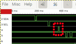
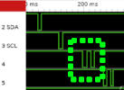
Can compare good vs bad results on pin 4 on two different RPis. You see the red highlighted one on pin4 failed to go high or pull down/up. The green/good example on another pi shows pin 4 went high and passed the pulldown test.
Then used a multi-meter to measure voltage in all 4 modes. Pins with bad pullup/pulldown internal resistors did not go to the intended 0 or 3.3V. GPIO 24 is a good pin for comparison.

NodeRed
Node Red RPi functions are another quick way to test the different modes. It is not as thorough but quicker.
- For output you can check hi/lo or PWM (use an o-scope to see results)
- For input you can toggle between pulldown and pullup resistor to confirm it moves from 0-3.3V. Can use a multimeter or led to see the result.
- You inject an input like 1(hi) or 0(lo) with a multimeter or led connected to the pin to watch its response.
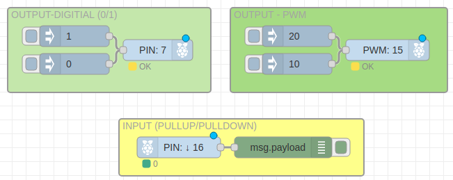
Node Red code below is for importing into node red
[{"id":"706510fe.1755a","type":"tab","label":"Flow 1","disabled":false,"info":""},{"id":"47f6d9a9.6d86c8","type":"group","z":"706510fe.1755a","name":"OUTPUT - PWM","style":{"label":true,"fill":"#addb7b"},"nodes":["ac9df3b9.6814a","95f23903.8359d8","ea6f64c4.58dc18"],"x":654,"y":139,"w":312,"h":122},{"id":"a65846a0.950598","type":"group","z":"706510fe.1755a","name":"OUTPUT-DIGITIAL (0/1)","style":{"label":true,"fill":"#c8e7a7"},"nodes":["3d763c68.d3c4c4","daacaf30.bc261","bf6bc9a6.43e5b8"],"x":334,"y":139,"w":292,"h":122},{"id":"ae60ca9f.edea08","type":"group","z":"706510fe.1755a","name":"INPUT (PULLUP/PULLDOWN)","style":{"label":true,"fill":"#ffff7f"},"nodes":["71d1e9d1.027e38","63e531c7.f632"],"x":494,"y":299,"w":352,"h":82},{"id":"3d763c68.d3c4c4","type":"rpi-gpio out","z":"706510fe.1755a","g":"a65846a0.950598","name":"","pin":"7","set":false,"level":"0","freq":"50","out":"out","x":550,"y":200,"wires":[]},{"id":"daacaf30.bc261","type":"inject","z":"706510fe.1755a","g":"a65846a0.950598","name":"","props":[{"p":"payload"},{"p":"topic","vt":"str"}],"repeat":"","crontab":"","once":false,"onceDelay":0.1,"topic":"","payload":"1","payloadType":"num","x":430,"y":180,"wires":[["3d763c68.d3c4c4"]]},{"id":"bf6bc9a6.43e5b8","type":"inject","z":"706510fe.1755a","g":"a65846a0.950598","name":"","props":[{"p":"payload"},{"p":"topic","vt":"str"}],"repeat":"","crontab":"","once":false,"onceDelay":0.1,"topic":"","payload":"0","payloadType":"num","x":430,"y":220,"wires":[["3d763c68.d3c4c4"]]},{"id":"ac9df3b9.6814a","type":"inject","z":"706510fe.1755a","g":"47f6d9a9.6d86c8","name":"","props":[{"p":"payload"},{"p":"topic","vt":"str"}],"repeat":"","crontab":"","once":false,"onceDelay":0.1,"topic":"","payload":"20","payloadType":"num","x":750,"y":180,"wires":[["ea6f64c4.58dc18"]]},{"id":"71d1e9d1.027e38","type":"rpi-gpio in","z":"706510fe.1755a","g":"ae60ca9f.edea08","name":"","pin":"16","intype":"down","debounce":"25","read":true,"x":580,"y":340,"wires":[["63e531c7.f632"]]},{"id":"63e531c7.f632","type":"debug","z":"706510fe.1755a","g":"ae60ca9f.edea08","name":"","active":true,"tosidebar":true,"console":false,"tostatus":false,"complete":"false","statusVal":"","statusType":"auto","x":730,"y":340,"wires":[]},{"id":"95f23903.8359d8","type":"inject","z":"706510fe.1755a","g":"47f6d9a9.6d86c8","name":"","props":[{"p":"payload"},{"p":"topic","vt":"str"}],"repeat":"","crontab":"","once":false,"onceDelay":0.1,"topic":"","payload":"10","payloadType":"num","x":750,"y":220,"wires":[["ea6f64c4.58dc18"]]},{"id":"ea6f64c4.58dc18","type":"rpi-gpio out","z":"706510fe.1755a","g":"47f6d9a9.6d86c8","name":"","pin":"15","set":false,"level":"0","freq":"50","out":"pwm","x":880,"y":200,"wires":[]}]
ESP32
For the esp32 you’ll need a quick micropython script that test the different modes of the pin. It’s a fairly manual test. You have a few options for measuring the voltage
- External multi-meter and write down the result
- External o-scope and write down the result
- Or esp32 pins on the esp32 itself to measure the voltage and PWM (ie pins 34 and 15 below)
Input/Output check
- Check input voltage with internal up/down resistors using one of options above
- Check input reading with PWM frequency (will need a PWM frequency meter like XY-PWM or use one of the pins to create a PWM signal).
- Check output voltage at both hi/lo state.
- Check output PWM (will need an o-scope or use one the pins to measure the PWM signal)
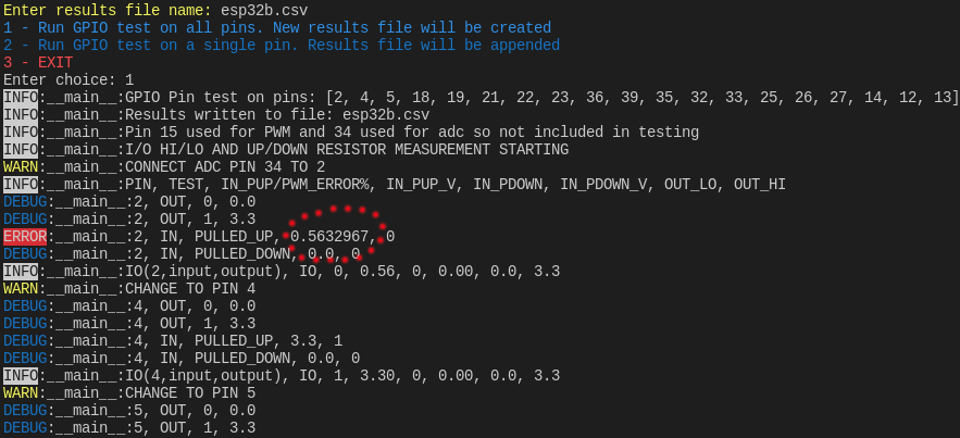
I wrote a script to check the esp32 pins using the on-board ADC/PWM. I use pin 34 for ADC and pin 15 for PWM (but you can change it in the code). It’s located on github.
After each test there is a pause to move either the ADC or PWM lead to the next GPIO pin to be tested. I keep the final results file in my project folder so I can quickly reference which pins on which esp32 device should not be used.
Note - reading the pins, especially at higher frequencies, is less accurate than creating a PWM signal.
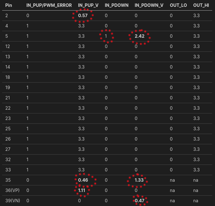
Below are example results for the I/O portion
