Intro to raspberry-pi
Raspberry Pi Hardware
Raspberry Pi is the most common component in my projects so I’ll include more details on setting up its hardware. It can have multiple purposes; used as a PC/laptop to do coding with or the device/controller of a project that loops thru and executes the codes (take measurements, turn relay switches on/off) or as a server that sends/receives messages or all at the same time.
A great resources on the Raspberry Pi Hardware is at raspberrypi.com
RPi Imager
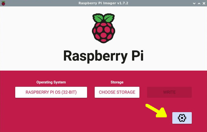
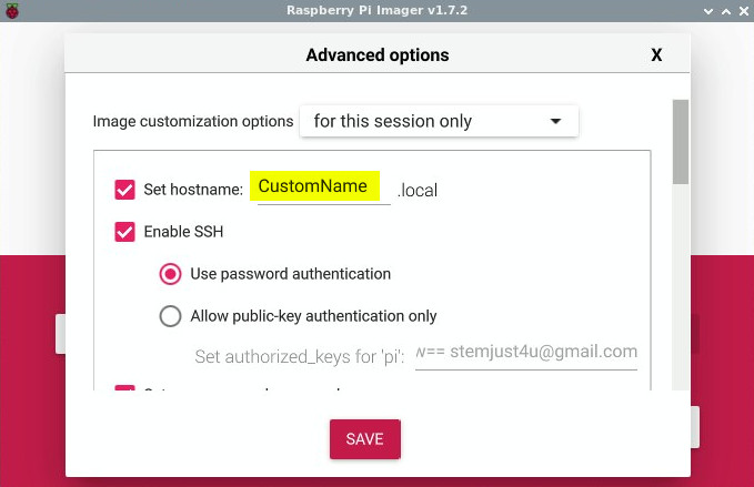
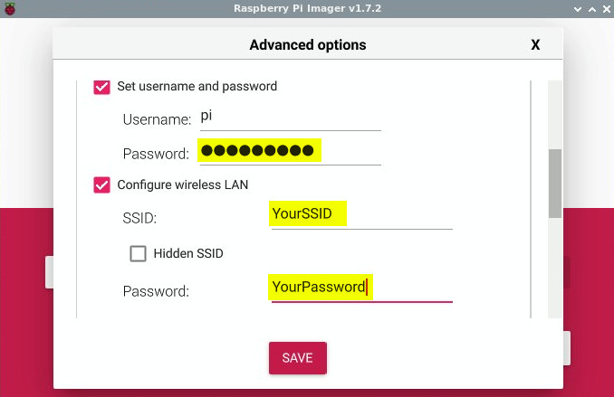
Much of the setup info below was before the Raspberry Pi Imager. With the RPi Imager you can set many of the settings below (ssh, user name password, wifi SSID/password) during the SD card setup.
Micro SD card
- Instead of a hard drive the RPi uses a micro SD card to store the O/S and files
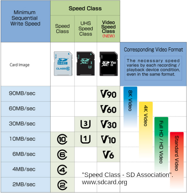
- Speed - Class 10 or UHS class 1 are good options and inexpensive
- Capacity - 16GB is more than enough for a project oriented Pi. 32-64GB is good when used as a PC and installing other OS like Ubuntu
- For installing the Raspberry Pi OS (or Ubuntu) the Raspberry Pi Imager has made it very easy
- One differences between a cheap card and nice Sandisk/Samsung is that a 16GB cheap SD card will be on the lower side for storage capacity (15.9 GB vs a full 16GB). This is important if you’re trying to copy an image that requires full 16GB of space. It’s good to have some higher quality SD cards for that purpose.
Monitor options
See Monitor link for more details
- Monitor (15” and larger work best if doing much coding on it)
- Headless (you use a PC/laptop to VNC or remote into the RPi). This is made easy by the fact RealVNC has a free Raspberry Pi option pre-installed.
- If using a new monitor there shouldn’t be issues with just plugging in a HDMI cord. Should be plug-n-play. When using older, cheaper monitors I’ve had to adjust the /boot/config.txt settings. (note - RPi4 has the option for dual monitor setup which is useful when coding)
- Smaller, touch screen displays. May need to install libraries to make them work.
Power Supply
(can normally use good phone chargers)
- Pi0-3 = 5.1V (2-2.5A) micro USB
- Pi4 = 5.1V (3A) type C
- There are other power options (ie thru the pins, POE) but become more involved
- The RPi0-3 can be powered with a decent 5.1V and 2-2.5A (>10W) power supply (phone charger, battery, etc) using micro-USB. Many phone chargers with 2A listed will work fine. However if the voltage on the power supply fluctuates below 5-5.1V you will get a low voltage symbol on the Pi (yellow lightning bolt). Another factor is the charging cord. If using a cheaper/thinner cord that is long (increased resistance) the voltage at the RPi may drop below 5V resulting in the low voltage symbol. Most of my charging bricks/cords work fine but there have been a few that caused problems. (side note - many micro USB cords are power only, do not have data lines. If wanting to transfer data over USB make sure the cord has data lines)
Power Guide-lines
- RPi0-3 >10W (5.1V,2-2.5A)micro-USB
- RPi4 >15W (5.1V,3A)USB-C
- Watts(Power)=I(current A)xV(voltage)
Sound
- The Pi uses PWM or PCM hardware for sound.
- PWM (headphone jack, med quality)
- PCM (Pulse-code Modulation) uses GPIO18(CLK), 19(FS), 20(DIN), and 21(DOUT). Produces higher quality sound when sent to a DAC.
- HDMI or USB adapter is also an option.
Keyboard/Mouse
- Wireless keyboard mouse are a good option. Bluetooth keyboard/mouse now work well with RPi.
- compose key info is in conky section (alt-o-o give you ° and alt-u-/ gives you µ)
There are some command lines in the Hardware section. Details will be covered more in the Software sections but until then it will help to know a couple terms.
sudois how you edit a file that requires root (aka administrator) privileges.nanois a common text editor. So$ sudo nano <path/to/file>is a common command you type in a terminal to edit a file with root (administrator) privileges. I will be omitting the $ to make copying lines quicker. Inside nano you can use the arrow keys to move around and edit the text. There is a help menu at the bottom. (ie. ctrl-X will exit out and give you the option to save)
If setting up a new Raspberry Pi for a project.
- Use RPi imager to install the Raspberry Pi OS on the SD card. (I usually install the full version and then remove programs I do not need)
- Plug the RPi and go through the setup screens and turn on VNC (if you didn’t already turn it on in the rpi imager settings).
- After reboot you can note the IP address and use it with RealVNC viewer to connect remotely from a desktop PC/laptop.
- To free up space and minimize the time required for updates I remove programs I will not use. See bottom of my list of software page.
- optional - change the RPi appearance/desktop and/or customize the desktop start at RPi options.
- For details on how installing packages work continue on to software package section
A nice feature of having the OS on the SD card is you can easily keep back up images of a Raspberry Pi setup after installing s/w and customizing your setup. Then you can burn that image on to a new SD card to recover or setup a 2nd RPi with similar software. RPi has a card copier app, or you can use Etcher or there are other methods too (including ways of shrinking the image file). You can also have one SD card with Raspberry Pi OS and another SD card with Ubuntu for swapping between OS’s.
The spec table below lists what kind of power draw you can expect on a Pi. Notice the power usage is much smaller than the power requirement listed on the power supplies above. That is because it is always good practice to have some buffer. The Pi will have ‘power spikes’ when it boots up and when programs you’re running push the CPU’s to higher utilization. Also the number of items you have plugged in to USB and HDMI ports will affect the total power requirement.
Understanding the power usage of your setup becomes more critical when working on a solar or battery project. You will need to measure the power usage of that specific set-up and then add in some buffer. Typically your project will use a little more power than you expected and your power source will provide a little less power you than you expected.
A USB multimeter is a useful, inexpensive tool for measuring voltage from a USB power supply and the power usage of your set up. Look for a meter that gives time over amps.
- First reset the time to 0
- Plug the multimeter it into your power supply (solar/battery/wall charger), and plug your project (RPi/circuits) into the other end.
- Now, while your project is plugged in, you can measure how many amps are used over a specific period of time or Amp-hour (Ah). Multiply by voltage to get Watt-hour (Wh). For example. If multimeter shows the project used 800mA over 1.5 hrs. (800mA = 0.8A) 0.8A/1.5hr = .53Ahr (multiply by 5.1V to get 2.72Wh) For reference a li-on power bank may have a capacity of 11Watts. Your project uses 2.72Wh, so your project could run for almost 4 hours on that power bank. (11Wh/2.72Wh = 4.04 hours)
CPU/Memory/Power Compare
Raspberry Pi and ESP32 Specs This is a quick summary to help decide which device is best for your projects based on processor, memory, and power usage. Also helps when downloading packages .. for example Raspberry Pi is a arm type, not a x86/x64 or amd64. All RPi and ESP32 listed below have built in wi-fi and bluetooth. (attiny85 does not) Raspberry Pi’s require SD card (16GB is good for projects. 32-64GB is good for using as a PC and installing another OS like Ubuntu.
More details below are on the Benchmarking page. There are more RPi models but I only list versions I keep around for projects and I include ESP32 for reference. A good link to compare all the Raspberry Pi models, including original Pi (arm1176) and RPi2 (armv7), is at socialcompare
| model | core | cpu | ARM | arm | Hz | RAM | Power Usage* |
|---|---|---|---|---|---|---|---|
| attiny85 | single | Atmel/Microchip | AVR/RISC | 8Bit | 20MHz | 512B | <0.1 Watts |
| esp32 | single/dual | Xtensa | na | na | 160/240MHz | 4MB | 0.2/0.25/0.3 Watts |
| pi0w | single core | Broadcom2835 | ARM1176 | armv6 | 1GHz | 512MB | 0.7/1.2 Watts |
| pi3A+ | quad core | Broadcom2837B0 | Cortex-A53 | armv8 | 1.4GHz | 512MB | 1.2/2.3 Watts |
| pi3B | quad core | Broadcom2837 | Cortex-A53 | armv8 | 1.2GHz | 1GB | 1.3/2.5 Watts |
| pi3B+ | quad core | Broadcom2837B0 | Cortex-A53 | armv8 | 1.4GHz | 1GB | 1.7/3.0 Watts |
| pi4 | quad core | Broadcom2711 | Cortex-A72 | armv8 | 1.5GHz | 2,4,8GB | 3.5/5.0 Watts |
Low side is idle and high side is using programs. Numbers are estimated. Does not include max power when powering up or other spikes. RPi4 can run up to 2.1GHz when over-clocked
attiny85 and esp32 (including esp01/esp8266) are more microcontroller vs the Raspberry Pi which is closer to a microprocessor. attiny85 and esp do not run a operating system. The attiny85 does not have built-in wifi. It only has 6 I/O pins but runs at a very low power usage. I use it for simple circuit projects. (The 4 pins can be used for digital I/O, or 10-bit ADC, or PWM.) Arduino can be used to program it (I had problems programming it with Linux and had to use my windows 10 PC)
Power usage of esp32 is smaller than Raspberry Pi. When processing actions will vary (0.3-0.5Watts). When idle will vary based on CPU speed you set. 240MHz is fastest (dual core). Approx 80-240Mhz will use 0.2-0.3W at idle. (Negative impact is that lower CPU will significantly increase time to run main loop.) When using sleep mode can get below 0.1W.
Notes for RPi4
- Has dual display ports (having 2 screens is nice for working on projects)
- Most likely need a fan and heat sink
- Requires larger power supply and type-C charging cord.
Other notes
- Memory - Pi4=LPDDR4, Pi3=DDR2
- Pi0 (armv6) is 32bit only
- Pi3/4 (armv8) is 32/64bit (Raspberry Pi OS is currently only 32bit. There are 64bit OS options though. See Raspberry Pi OS section)
- Pi0-3 use Broadcom VideoCore IV, Pi4 has VideoCoreVI
- Pi0 the CPU has access to GPU L2 cache (other Pis ARMs have their own L2 cache)
- armhf = arm (hard float)
My general notes when picking for a project.
- If using ADC (analog to digital) and low power then ESP32 is good.
- Raspberry Pi 0 (Zero) is great for low power projects that require more computing power than a ESP32. (ie. a camera hooked to a RPi0 can be used for security cam projects.) Can not remote connect with VS Code for programming
- Raspberry Pi 3A+ is a good middle-of-road Pi. Useful when you need more processing power than a RPi0 and lower power usage than a RPi3/4. Can remote connect with VS Code making the programming easy
- Raspberry Pi 3/4 have the most processing/memory but also cost more and use more power. Comes down to balancing the purpose and requirements of the project. Raspberry Pi 4 with 4-8GB of RAM and 32-64GB SD card can be used to experiment with other OS like Ubuntu.
Over Clocking
RPi4
Over-clocking the RPi4 will give noticeable performance boost. In addition to updating the CPU freq in your config file you will need a heat sink and fan to keep the temp down (RPi4 will run hot). More details on fan setup are below. Config file locations for both Raspberry Pi OS and Ubuntu are below.
Update Raspberry Pi config file sudo nano /boot/config.txt
# uncomment to overclock.
# 700 MHz is default
over_voltage=6
arm_freq=2050
Update Ubuntu config file sudo nano /boot/firmware/config.txt
# uncomment to overclock.
# 700 MHz is default
over_voltage=6
arm_freq=2050
If you do not see a commented out section for the arm_freq you can add the text anywhere.
I first tried 2100 MHz but the Pi was frequently shutting down. Freq of 2050 is where I had the best performance. I use conky to monitor the speed and temp. Some good articles on over-clocking are MagPi and RaspberryPi.org
RPi3B
Over clocking settings to try on RPi3
# GPU freq
core_freq=500
# CPU freq
arm_freq=1300
# 1.3V
over_voltage=4
disable_splash=1
Raspberry Pi 4 Fan
If over-clocking the RPi4 it would be good to add a heat sink. You can also add a fan to but I have ran without a fan and not had issues. When the CPU is at high usage the temp will get up to 80°C for a short period but throttling doesn’t occur until 85°C. Adding a fan will keep the temp below 55°C. I have tried both a cheap $5 dollar fan and a Argon one case with built-in fan. Both have worked fine but I prefer the Argon one case. Argon one was mostly a plug-in-play setup and looks nice. More details on fan setup are below. RPi4 Fan Setups on Amazon
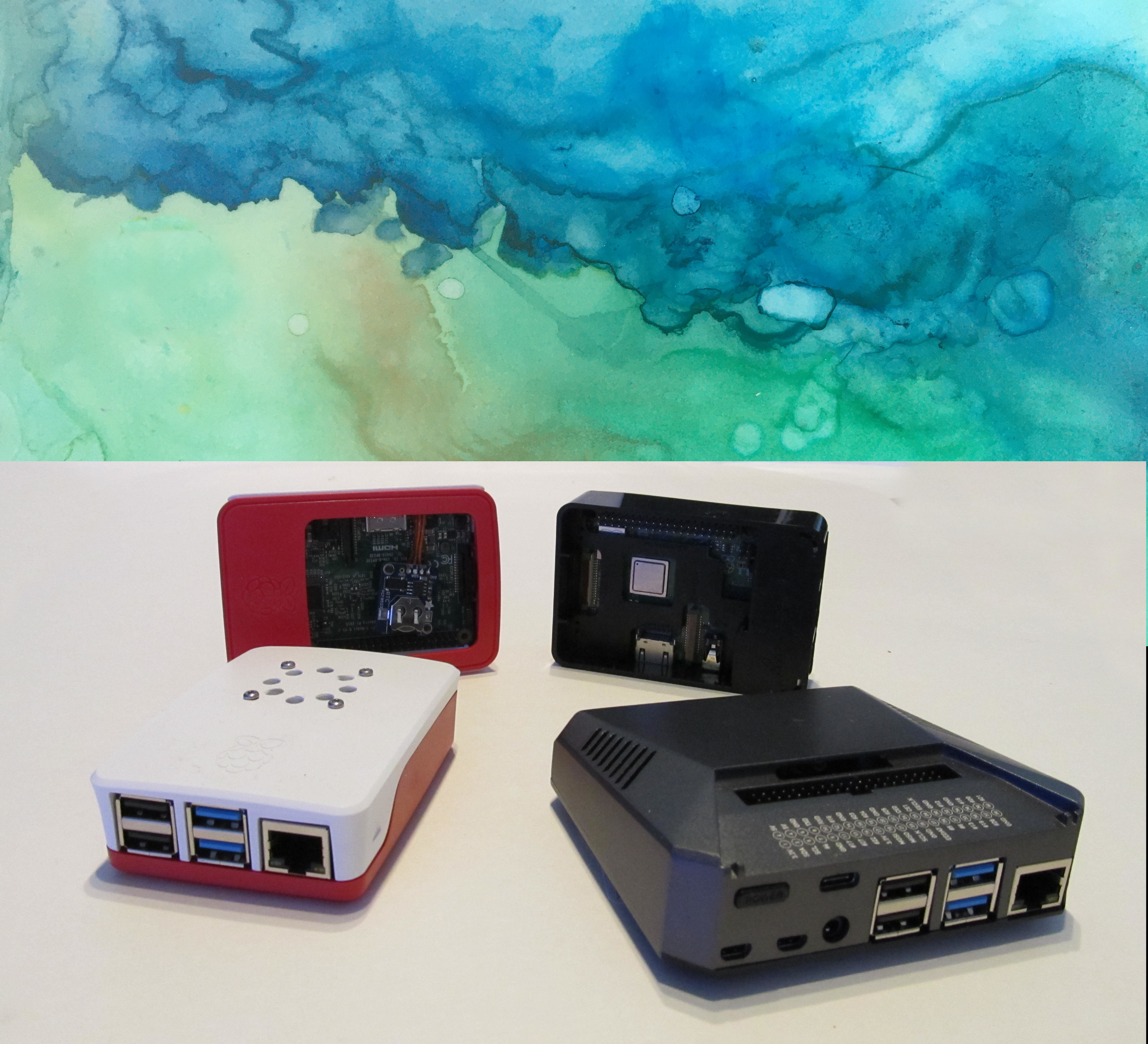
DIY Fan Setup is red/white Pi on left (with automatic temp control of on/off) With the more recent Raspberry Pi OS the DIY fan setup is easier. But you will need either
- 3-wire fan (5V, GRND, GPIO control)
- or a 2-wire fan (5V and GRND) and then solder a general purpose NPN transistor on the GRND side. (will also need a 10k resistor). The GPIO will connect to the NPN transistor and switch the fan (thru GRND) on/off.
Newer Raspberry Pi OS now has settings for the control portion in ‘Raspberry Pi Configuration’ then ‘Performance’ and ‘Fan’. One thing to consider is that you will lose access to some pins with this setup.
Argon One Case with Fan (gray metallic case on right)
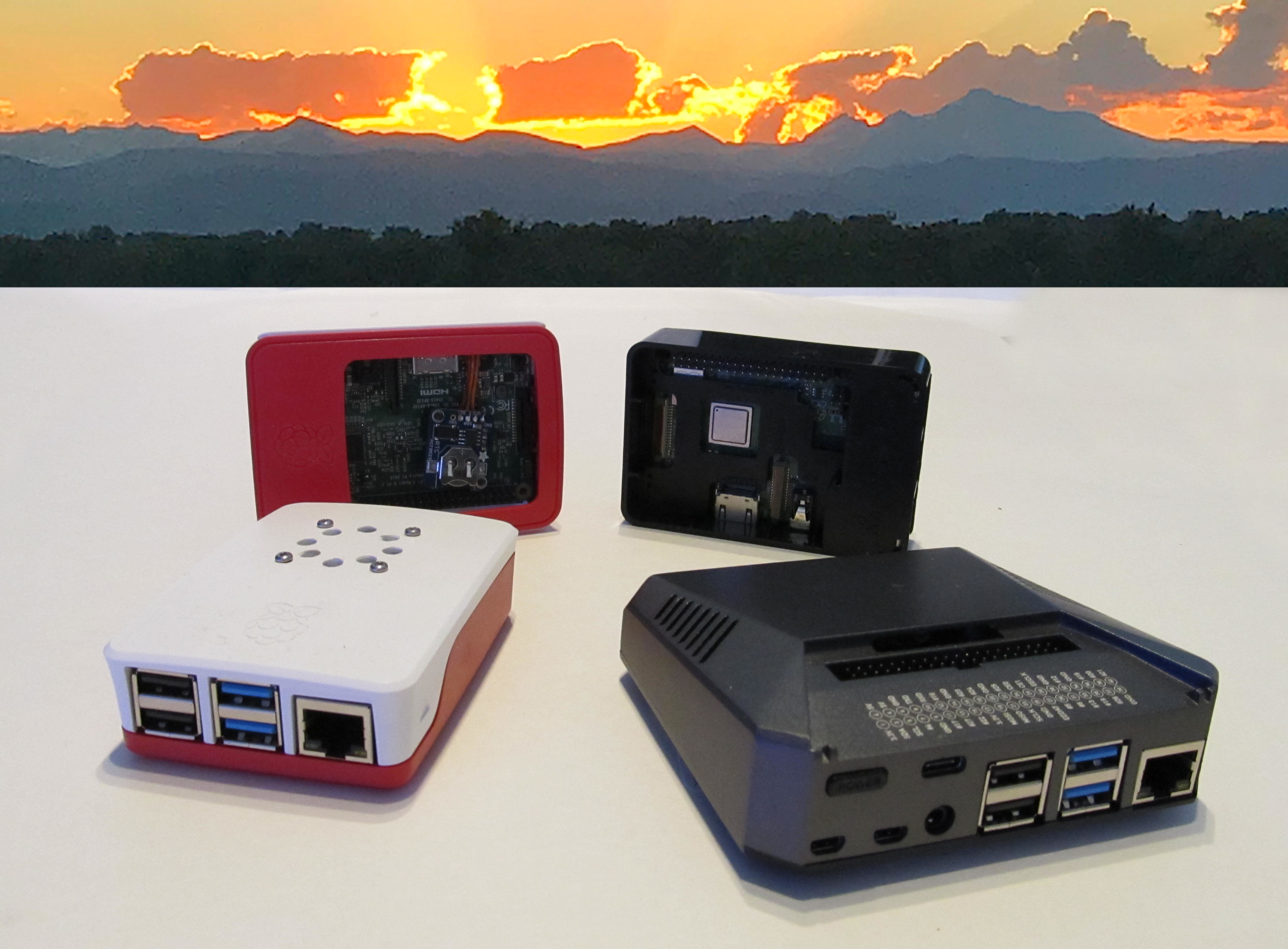
The Argon One setup has a built-in fan. You do not lose access to any pins and you only need to install their configuration program to get it running. (no wiring/soldering required)
After installing the RPi4 in the case Raspberry Pi OS setup/install
curl https://download.argon40.com/argon1.sh | bash
To manually update temp/fan settings
argonone-config
Desktop icon/app should be installed
Ubuntu setup/install from meuter
cd /tmp/
wget https://raw.githubusercontent.com/meuter/argon-one-case-ubuntu-20.04/master/argon1.sh
chmod a+x argon1.sh
sudo ./argon1.sh
To manually update temp/fan settings use
argonone-config
To create desktop icon look at example in Desktop Icon section
Raspberry RTC (real time clock)
RPis do not come with a RTC. But you can easily add one.
- Enable I2C communication in
sudo raspi-config - Physically install the RTC and reboot
- Run
sudo i2cdetect -y 1(should see it show up as 68) - Now add the chip you’re using (ds3231, ds1307, pcf8523) to the end of the config file
-
sudo nano /boot/config.txtand adddtoverlay=i2c-rtc,ds3231(or add ds1307 or pcf8523 for which one you’re using) - If you reboot and run i2cdetect again it should show as UU
- Now remove the fake clock
sudo apt -y remove fake-hwclocksudo update-rc.d -f fake-hwclock removesudo systemctl disable fake-hwclock
Remove from start up script
sudo nano /lib/udev/hwclock-set- Comment out these lines with #
#if [ -e /run/systemd/system ] ; then # exit 0 #fi #/sbin/hwclock --rtc=$dev --systz - You can check the time of the RTC module with
sudo hwclock -r - You can check the time of the RPi with
date - If the RPi date is correct (connected to wifi) you can write the date/time to the RTC module with
sudo hwclock -w- Now read the RTC module again and it should be correct
sudo hwclock -r