Intro to SPI I2C communication
Communication Types
Communicating with SPI, I2C, UART (I2S for digital audio) Below describes different communication methods between a RPi and an external device. PISCOPE is a great way to see the waveforms (hi/lo sequences). (SPI example below)

Device Tree is how the Pi supports multiple hardware configurations with a single kernel. To enable hardware interfaces use $ sudo raspi-config and go to interfaces
You can also see in /boot/config.txt
dtparam=i2c_arm=on
dtparam=i2s=on
dtparam=spi=on
enable_uart=1
dtoverlay=w1-gpio # One-wire communication. Can use with DS18B20 temp sensor
Default is pin 4. Can change with
dtoverlay=w1-gpio,gpiopin=x
or use command $ sudo modprobe w1-gpio
Can see devices discovered via 1-wire busses
$ ls /sys/bus/w1/devices/ Typically use 4.7k pull-up resistor between GPIO and 3.3V.
Note - multiple factors affect the speed of data transfer. Data speed is mainly for comparison.
SPI
SPI is synchronous serial communication (serial peripheral interface) at medium or high speed. (32kbps-8Mbps) Typically use 4 wires
- MOSI or Din (master out slave in, send data from master to the device)
- MISO or Dout (master in slave out, master receives data from the device)
- SCLK (clock)
- CS or CE (Chip select, SS, used to select the device) Since SPI uses separate lines for receiving/transmitting it theoretically can be faster (Mbps) than I2C but requires more wires.
- SPI0 is enabled with dtparam=spi=on (cs = GPIO 8, 7)
- SPI1 is enabled with (1cs, 2cs, 3cs for number of chip select lines)
dtoverlay=spi1-1cs,cs0_pin=16 # change from 18 to 16ordtoverlay=spi1-3cs # three chip select lines (GPIO 18, 17, 16)

SPI Example
import spidev

spi = spidev.SpiDev()
spi.open(0, 0) # bus 0, the second 0 can be 0 or 1 for CS0 or CS1.. can have multiple devices
spi.max_speed_hz = 1000000

channel = 0
r = spi.xfer([1, (8+channel) << 4, 0])
value = ((r[1]&3) << 8) + r[2]
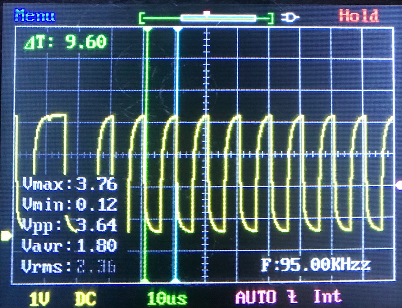
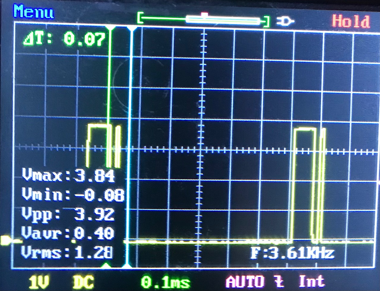
SPI example from o-scope with MCP3008 (clock and data/MISO). Can use o-scope to confirm signal to Pi (MISO) is 3.3V and not 5V (Pi GPIO not rated for 5V)


I2C
I2C (I squared C) is another synchronous serial communication (medium speed).
- It only uses two bidirectional lines.
- SDA (serial data line, half-duplex, send/receive must alternate)
- and SCL (serial clock line). Theoretical data transfer speed is slower (100kbps, 400kbps, etc) than SPI but requires fewer wires.
- The Pi will initiate the transfers. Data=GPIO2, Clock=GPIO3. I2C speed on RPi = 100KHz
- Pins: GPIO2(SDA) and GPIO3(SCL). Data sent in 8 bit bytes. Some tools
$ sudo apt-get install i2c-tools python-smbus
$ sudo i2cdetect -y 1

By Marcin Floryan - Own work, Public Domain
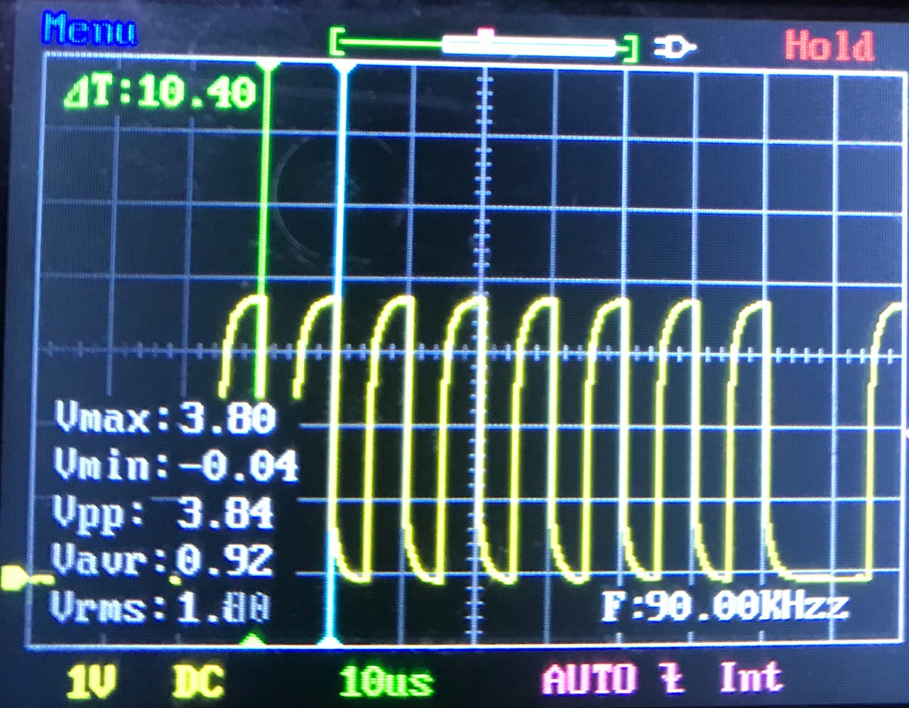
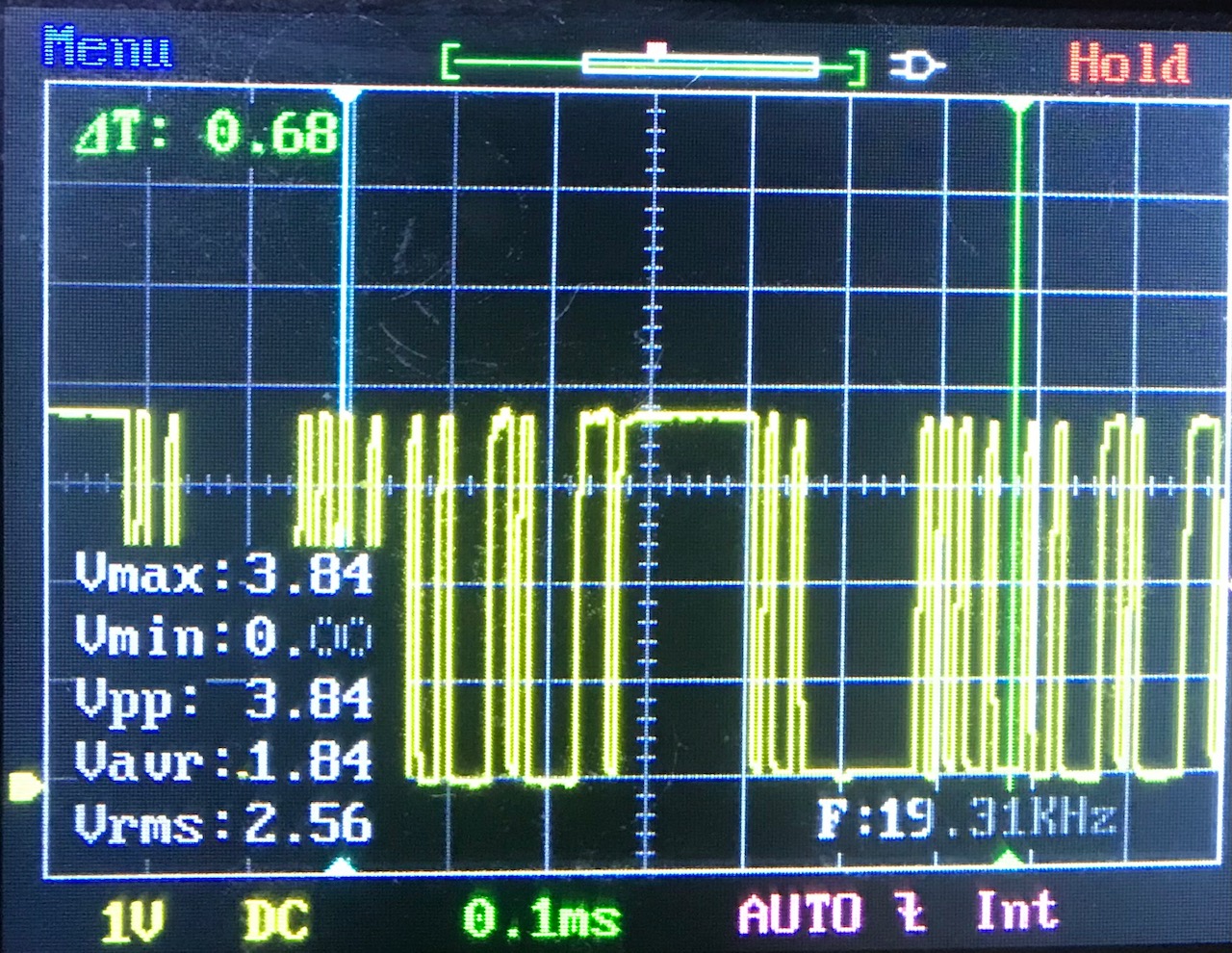
I2C example with ADS1115 (clock and data)


I2C Example from https://pinout.xyz/pinout/i2c
import smbus
DEVICE_BUS = 1
DEVICE_ADDR = 0x15
bus = smbus.SMBus(DEVICE_BUS)
bus.write_byte_data(DEVICE_ADDR, 0x00, 0x01)
I2S
I2S (I squared S) is different than I2C. I2S is used for PCM (pulse code modulation) audio where low jitter is needed. It uses a
- word-select (WS)
- clock (SCK)
- data line, multiplexed serial data line (SD). PCM is a method to digitally represent analog signals. By wdwd - Own work, CC BY 3.0 CLK = GPIO 18 DIN = GPIO 20 DOUT = GPIO 21 FS = GPIO 19

UART (serial)
Universal Asynchronous Reception and Transmission.
- Often thru USB-to-serial converter, acting as if the USB is a serial port.
- The Pi or device can initiate data transfer. Data is transmitted/received one bit a time, sequentially, without a clock.
- Instead of clock, start/stop bits are used to synchronize.
- Have to pay attention to the TTL (transistor-transistor-logic) level. Pi uses 3.3V, vs Arduino 5V TTL or RS232 which could vary from -25 to +25V (travel longer distance than I2C/SPI).
- If using pins for receiving/transmitting: RX(GPIO15) and TX(GPIO14). RX goes to TX, TX goes to RX between devices. Speed is medium/low in 8 bit bytes (start, 8 data bits, stop). There is no parity.

By Plugwash at en.wikipedia. - Transferred from en.wikipedia, Public Domain
When using USB and device is connected can use these commands.
$ ls -l /dev/ttyUSB*
crw-rw---- 1 root dialout 188, 0 Apr 6 12:41 /dev/ttyUSB0
To find out if Pi is in the group dialout use
$ id (typically only an issue if using non Raspberry Pi OS)
To add
$ sudo usermod -a -G dialout pi
Serial communication usually done with TTL.
- Baud is data rate or how fast the data can be sent over the serial line or number of bits per second(bps). ie 9600bps, 115200bps (can vary from 50 to 230400). Both devices should use the same Baud rate.
- Logic high, 1, will be Vcc
- Logic low, 0, will be 0V
- (Parallel interface would be able to transmit multiple bits at a time but requires many more wires)
Wiringpi example from https://pinout.xyz/pinout/i2c
import wiringpi
wiringpi.wiringPiSetup()
serial = wiringpi.serialOpen('/dev/ttyAMA0',9600)
wiringpi.serialPuts(serial,'hello world!')

By Plugwash at en.wikipedia. - Transferred from en.wikipedia, Public Domain